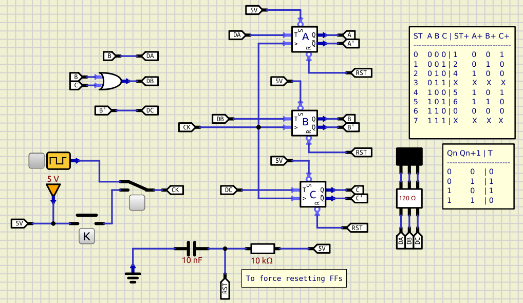
I'm going nuts with this circuit!!!!
Quote from blitobyte on September 7, 2024, 10:44 amCan anybody help me?
I'm on a sequential circuits course and I have to design a circuit with three T Flip-flops which states go : 0->1->2->4->5->6->0. States 3 and 7 are forbidden.
My solution coincides with the teacher's but not with simulIDE. What am I doing wrong?
Can anybody help me?
I'm on a sequential circuits course and I have to design a circuit with three T Flip-flops which states go : 0->1->2->4->5->6->0. States 3 and 7 are forbidden.
My solution coincides with the teacher's but not with simulIDE. What am I doing wrong?

Quote from arcachofo on September 7, 2024, 11:23 amHi.
The circuit is working ok for me, lines A, B, C fit the truth table.
But Leds are connected to DA, DB, DC.
Hi.
The circuit is working ok for me, lines A, B, C fit the truth table.
But Leds are connected to DA, DB, DC.
Quote from blitobyte on September 7, 2024, 2:45 pmWhen you say the circuit is working OK for you, what do you mean? LEDS have to be connected to DA, DB and DC, don't they? They should turn on successively showing the corresponding 'numbers':
001, 010, 100, 101, 110, 000 ... and on
or a least that's what I expect. In fact, a similar circuit with FF-D work perfectly. Sending you the circuit
When you say the circuit is working OK for you, what do you mean? LEDS have to be connected to DA, DB and DC, don't they? They should turn on successively showing the corresponding 'numbers':
001, 010, 100, 101, 110, 000 ... and on
or a least that's what I expect. In fact, a similar circuit with FF-D work perfectly. Sending you the circuit
Uploaded files:Quote from arcachofo on September 7, 2024, 3:04 pmWhen you say the circuit is working OK for you, what do you mean?
I mean just what I said: " lines A, B, C fit the truth table."
LEDS have to be connected to DA, DB and DC, don't they? They should turn on successively showing the corresponding 'numbers':
001, 010, 100, 101, 110, 000 ... and on
What I see in the truth table is A,B,C, not DA,DB,DC
So if you want to check the Leds against the truth table you should connect the Leds to A,B,C, isn't it?
Or am I missing something?
When you say the circuit is working OK for you, what do you mean?
I mean just what I said: " lines A, B, C fit the truth table."
LEDS have to be connected to DA, DB and DC, don't they? They should turn on successively showing the corresponding 'numbers':
001, 010, 100, 101, 110, 000 ... and on
What I see in the truth table is A,B,C, not DA,DB,DC
So if you want to check the Leds against the truth table you should connect the Leds to A,B,C, isn't it?
Or am I missing something?
Quote from blitobyte on September 7, 2024, 5:53 pmSorry, perhaps it's me who is missing something. I don't want to check the LEDS against the truth table. What I want is to show the circuit states (0,1,2,4,5,6,..) through the LEDS.
I may be wrong, but what I understand is that the functions that describe the Flip-Flop behaviours: DA, DB, DC; calculated from the truth tables and the Karnaugh maps applied to the LEDS should show the FF's states, shouldn't it?
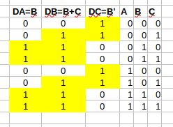
As a matter of fact, SimulIDE is actually showing what the functions say. Have a look at the Excel. The headers are the functions (DA, DB, DC) and their values
So it must me who is missing something. Summing it up: How can I show the states of the circuit through LEDS? connecting them to the ABC values?
Sorry, perhaps it's me who is missing something. I don't want to check the LEDS against the truth table. What I want is to show the circuit states (0,1,2,4,5,6,..) through the LEDS.
I may be wrong, but what I understand is that the functions that describe the Flip-Flop behaviours: DA, DB, DC; calculated from the truth tables and the Karnaugh maps applied to the LEDS should show the FF's states, shouldn't it?
As a matter of fact, SimulIDE is actually showing what the functions say. Have a look at the Excel. The headers are the functions (DA, DB, DC) and their values

So it must me who is missing something. Summing it up: How can I show the states of the circuit through LEDS? connecting them to the ABC values?
Quote from blitobyte on September 7, 2024, 6:04 pmOK, you were right. If I connect the truth table values instead of the funcions DA, DB and DC, to the LEDS I get the expected behaviour. Now I have to reconsider it and understand it.
Thanks
OK, you were right. If I connect the truth table values instead of the funcions DA, DB and DC, to the LEDS I get the expected behaviour. Now I have to reconsider it and understand it.
Thanks
