
Does an IR sensor (tsop1738) or something that creates a series of bits exist
Quote from steinm on December 12, 2023, 2:13 pmI would like to simulate a circuit with input from an IR remote control. What would be the best way? I thought about an IR sensor like the tsop1738 and some way to configure it to output a sequence of low and high bits. Or maybe a generic generator of bit sequences?
I would like to simulate a circuit with input from an IR remote control. What would be the best way? I thought about an IR sensor like the tsop1738 and some way to configure it to output a sequence of low and high bits. Or maybe a generic generator of bit sequences?
Quote from arcachofo on December 12, 2023, 3:15 pmThere are several ways to do it. All depends in what exactly do you want to simulate.
If I understand correctly you just want to get some pulses (already demodulated) similar to what you would get out of a tsop17xx.
There is already something implemented to generate bit sequences from scripts in an efficient way.
But only 1 sequence is possible right now. I plan to add support for several sequences, but this is not done yet.In cases like like this with very low frequencies involved it could be done directly in the script.
How to implement this depends in the exact case, but you probably want a keypad or some buttons connected to the script component and write an script that read the inputs and generate the pulse train corresponding to that "command".
There are several ways to do it. All depends in what exactly do you want to simulate.
If I understand correctly you just want to get some pulses (already demodulated) similar to what you would get out of a tsop17xx.
There is already something implemented to generate bit sequences from scripts in an efficient way.
But only 1 sequence is possible right now. I plan to add support for several sequences, but this is not done yet.
In cases like like this with very low frequencies involved it could be done directly in the script.
How to implement this depends in the exact case, but you probably want a keypad or some buttons connected to the script component and write an script that read the inputs and generate the pulse train corresponding to that "command".
Quote from arcachofo on December 12, 2023, 9:52 pmAdded multiple sequences to IoPorts (Rev 2085).
Now it is possible to register many sequences from Scripts and trigger each one by: Port.trigger( n ).
The following code is a simple example of something like you want.
Just 2 buttons, each one triggers a different pulse sequence.
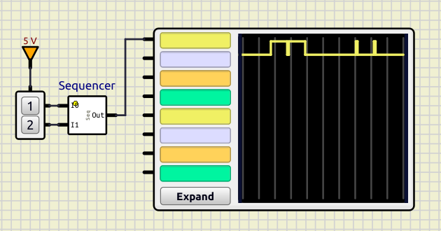
[spoiler title="Script generating 2 simple sequences:"]// PinModes: undef_mode=0, input, openCo, output, source IoPort@ inPort = component.getPort("PORTI"); IoPort@ outPort = component.getPort("PORTO"); void setup() { print("Sequencer init "); } void reset() { print("resetting Sequencer"); inPort.setPinMode( 1 ); // Input outPort.setPinMode( 3 ); // Output outPort.setOutState( 0 ); // Sequence 0 outPort.addSequence( {0,1e9,1e8,1e9} // Time in picoseconds , {1, 0, 1, 0} ); // Port state: 1 bit per pin // Sequence 1 outPort.addSequence( {0,1e8,1e9,1e8} // Time in picoseconds , {1, 0, 1, 0} ); // Port state: 1 bit per pin } void updateStep() { uint input = inPort.getInpState(); switch( input ){ case 1: outPort.trigger( 0 ); break; case 2: outPort.trigger( 1 ); break; } }[/spoiler]
This is the result:
Added multiple sequences to IoPorts (Rev 2085).
Now it is possible to register many sequences from Scripts and trigger each one by: Port.trigger( n ).
The following code is a simple example of something like you want.
Just 2 buttons, each one triggers a different pulse sequence.
// PinModes: undef_mode=0, input, openCo, output, source

IoPort@ inPort  = component.getPort("PORTI");
IoPort@ outPort = component.getPort("PORTO");

void setup()
{
    print("Sequencer init ");
}

void reset()
{
    print("resetting Sequencer");

    inPort.setPinMode( 1 ); // Input

    outPort.setPinMode( 3 );  // Output
    outPort.setOutState( 0 );

    // Sequence 0
    outPort.addSequence( {0,1e9,1e8,1e9}    // Time in picoseconds
                       , {1,  0,  1,  0} ); // Port state: 1 bit per pin
    // Sequence 1
    outPort.addSequence( {0,1e8,1e9,1e8}    // Time in picoseconds
                       , {1,  0,  1,  0} ); // Port state: 1 bit per pin
}

void updateStep()
{
    uint input = inPort.getInpState();

    switch( input ){
        case 1: outPort.trigger( 0 ); break;
        case 2: outPort.trigger( 1 ); break;
    }
}This is the result:
Quote from steinm on December 13, 2023, 8:15 amThanks, I will try that. In the meantime I created an mcu which reads the sequence from PGM similar to Scripted->Signal. That allows to put the sequence into a file for different IR remotes.
Thanks, I will try that. In the meantime I created an mcu which reads the sequence from PGM similar to Scripted->Signal. That allows to put the sequence into a file for different IR remotes.
Quote from arcachofo on December 13, 2023, 9:10 amIn the meantime I created an mcu which reads the sequence from PGM similar to Scripted->Signal. That allows to put the sequence into a file for different IR remotes.
Yes, that's a good idea.
But I'm changing the interface, registering a sequence with separate time and state is not good.
I want it to be like this, sending an array or pair values:
outPort.addSequence( {{0,1},{1e9,0},{1e8,1},{1e9,0}} );By now I can't figure out how to register a pair type in AngelScript, so I'm using an array of arrays:
array<array<uint64>>
In the meantime I created an mcu which reads the sequence from PGM similar to Scripted->Signal. That allows to put the sequence into a file for different IR remotes.
Yes, that's a good idea.
But I'm changing the interface, registering a sequence with separate time and state is not good.
I want it to be like this, sending an array or pair values:
outPort.addSequence( {{0,1},{1e9,0},{1e8,1},{1e9,0}} );
By now I can't figure out how to register a pair type in AngelScript, so I'm using an array of arrays:
array<array<uint64>>
Quote from arcachofo on December 13, 2023, 10:03 amChanged the interface to Port.addSequence( array<array<uint64>> sequence ) at Rev 2086.
Sequence is an array of pairs {time, state}.Note that the logic for each pair {time, state} is:
After "time" ps, set the Port State to "state" (1 bit per Pin).In this example values are hardcoded in the script, but can be read from PGM ( or RAM if you create it instead of PGM).
This is much more efficient than reading Memory and setting Port states from the script.
This script takes almost no cpu usage (all the work is done in C++) while Scripted->Signal is very cpu intensive.[spoiler title="Script that creates 2 sequences triggered by input Por values"]
// PinModes: undef_mode=0, input, openCo, output, source

IoPort@ inPort  = component.getPort("PORTI");
IoPort@ outPort = component.getPort("PORTO");

void setup()
{
    print("Sequencer init ");
}

void reset()
{
    print("resetting Sequencer");

    inPort.setPinMode( 1 );   // Input

    outPort.setPinMode( 3 );  // Output
    outPort.setOutState( 0 );

    // Sequence 0 : array or uint64 pairs {time, state}
    // Time in picoseconds, Port state: 1 bit per pin
    outPort.addSequence( {{0,1},{1e9,0},{1e8,1},{1e9,0}} );

    // Sequence 1: can be read from memory in a loop
    array<array<uint64>> sequence1(4);
    uint64 time;
    uint64 state;

    time  = 0;
    state = 1;
    sequence1[0] = {time,state};

    time  = 1e8;
    state = 0;
    sequence1[1] = {time,state};

    time  = 1e9;
    state = 1;
    sequence1[2] = {time,state};

    time  = 1e8;
    state = 0;
    sequence1[3] = {time,state};

    outPort.addSequence( sequence1 );
}

void updateStep()
{
    uint input = inPort.getInpState();

    switch( input ){
        case 1: outPort.trigger( 0 ); break;
        case 2: outPort.trigger( 1 ); break;
    }
}
[/spoiler]
Changed the interface to Port.addSequence( array<array<uint64>> sequence ) at Rev 2086.
Sequence is an array of pairs {time, state}.
Note that the logic for each pair {time, state} is:
After "time" ps, set the Port State to "state" (1 bit per Pin).
In this example values are hardcoded in the script, but can be read from PGM ( or RAM if you create it instead of PGM).
This is much more efficient than reading Memory and setting Port states from the script.
This script takes almost no cpu usage (all the work is done in C++) while Scripted->Signal is very cpu intensive.
// PinModes: undef_mode=0, input, openCo, output, source

IoPort@ inPort  = component.getPort("PORTI");
IoPort@ outPort = component.getPort("PORTO");

void setup()
{
    print("Sequencer init ");
}

void reset()
{
    print("resetting Sequencer");

    inPort.setPinMode( 1 );   // Input

    outPort.setPinMode( 3 );  // Output
    outPort.setOutState( 0 );

    // Sequence 0 : array or uint64 pairs {time, state}
    // Time in picoseconds, Port state: 1 bit per pin
    outPort.addSequence( {{0,1},{1e9,0},{1e8,1},{1e9,0}} );

    // Sequence 1: can be read from memory in a loop
    array<array<uint64>> sequence1(4);
    uint64 time;
    uint64 state;

    time  = 0;
    state = 1;
    sequence1[0] = {time,state};

    time  = 1e8;
    state = 0;
    sequence1[1] = {time,state};

    time  = 1e9;
    state = 1;
    sequence1[2] = {time,state};

    time  = 1e8;
    state = 0;
    sequence1[3] = {time,state};

    outPort.addSequence( sequence1 );
}

void updateStep()
{
    uint input = inPort.getInpState();

    switch( input ){
        case 1: outPort.trigger( 0 ); break;
        case 2: outPort.trigger( 1 ); break;
    }
}Quote from steinm on December 14, 2023, 7:07 amThat makes a lot more sense. So basically I need to create the sequences by reading the pulses from PGM during reset, and let SimulIDE take care of shifting it to the output? I still do not quite understand what
updateStep()does. When is it called?
That makes a lot more sense. So basically I need to create the sequences by reading the pulses from PGM during reset, and let SimulIDE take care of shifting it to the output? I still do not quite understand what updateStep() does. When is it called?
Quote from arcachofo on December 14, 2023, 8:58 amSo basically I need to create the sequences by reading the pulses from PGM during reset, and let SimulIDE take care of shifting it to the output?
Yes, you create the sequences, register the sequences in some por by: port.addSequence(). This is stored in the C++ side.
Then you trigger each sequence by: port.trigger( n ); where n is the index of the sequence in the order you created then.In this case the output port is only 1 bit, but it can be any size.
I still do not quite understand what
updateStep()does. When is it called?It is called when all the GUI stuff is updated, by default every 50 ms, but that is configured in settings->Circuit->Canvas Refresh.
This is convenient in this case because sequences are triggered with push buttons, so checking every 50 ms is ok.
In other cases you might want to trigger based in pin changes or a clock (like Scripted->Signal) or something else.
So basically I need to create the sequences by reading the pulses from PGM during reset, and let SimulIDE take care of shifting it to the output?
Yes, you create the sequences, register the sequences in some por by: port.addSequence(). This is stored in the C++ side.
Then you trigger each sequence by: port.trigger( n ); where n is the index of the sequence in the order you created then.
In this case the output port is only 1 bit, but it can be any size.
I still do not quite understand what
updateStep()does. When is it called?
It is called when all the GUI stuff is updated, by default every 50 ms, but that is configured in settings->Circuit->Canvas Refresh.
This is convenient in this case because sequences are triggered with push buttons, so checking every 50 ms is ok.
In other cases you might want to trigger based in pin changes or a clock (like Scripted->Signal) or something else.
Quote from steinm on December 14, 2023, 11:10 amWorks perfectly. In a first attempt I created a simple IR-Remote with10 buttons (though it could handle 15 buttons). It's a bit clumsy but sufficient for now. There are probably ways to put all this into a single component with a bunch of buttons and an output pin.
Works perfectly. In a first attempt I created a simple IR-Remote with10 buttons (though it could handle 15 buttons). It's a bit clumsy but sufficient for now. There are probably ways to put all this into a single component with a bunch of buttons and an output pin.
Uploaded files: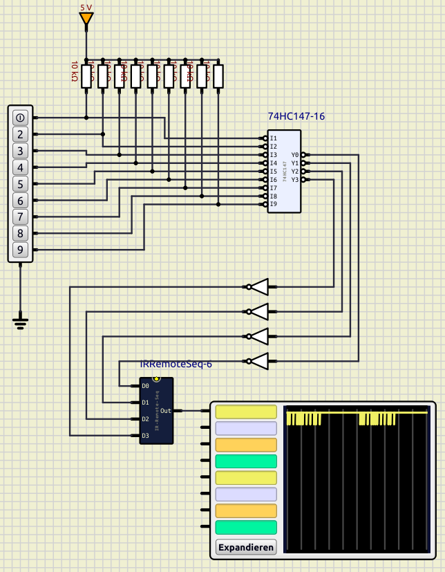
Quote from arcachofo on December 14, 2023, 11:13 amThere are probably ways to put all this into a single component with a bunch of buttons and an output pin.
Yes... put it all in a subcircuit type Board.
You can also do it with individual push switches and arrange them in the subcircuit as you want.
There are probably ways to put all this into a single component with a bunch of buttons and an output pin.
Yes... put it all in a subcircuit type Board.
You can also do it with individual push switches and arrange them in the subcircuit as you want.