
AVRasm2, Shape of Signal Edge to Trigger an External Interrupt
Quote from KerimF on March 10, 2024, 6:04 pmSimulIDE-R2220_Win32
Windows 7, 32
ATmega8The external interrupt 0, for example, is set to sense the falling edge at its pin.
This works fine if the interrupting signal is a square wave (5V-0V) generated by the Wave Generator component.But the MCU (as ATmega8) doesn’t detect the transition from high to low if it is somehow linear (slow, not abrupt) as shown below; the purple trace (5V to -0.42V in 1.3ms).
But I may have missed a certain setting.
Thank you.
SimulIDE-R2220_Win32
Windows 7, 32
ATmega8
The external interrupt 0, for example, is set to sense the falling edge at its pin.
This works fine if the interrupting signal is a square wave (5V-0V) generated by the Wave Generator component.
But the MCU (as ATmega8) doesn’t detect the transition from high to low if it is somehow linear (slow, not abrupt) as shown below; the purple trace (5V to -0.42V in 1.3ms).
But I may have missed a certain setting.
Thank you.
Quote from arcachofo on March 10, 2024, 6:33 pmHi.
Don't know what can be the problem , but INT0 and 1 falling edge are working for me no matter the speed of the input signal.
Check example attached.
Hi.
Don't know what can be the problem , but INT0 and 1 falling edge are working for me no matter the speed of the input signal.
Check example attached.

Quote from KerimF on March 10, 2024, 9:24 pmWould you please replace the manual voltage source with a 100 Hz triangular signal to flip an LED at every edge detection?
Please take your time, this is not urgent.
Thank you again for your continuous care.
Kerim
Would you please replace the manual voltage source with a 100 Hz triangular signal to flip an LED at every edge detection?
Please take your time, this is not urgent.
Thank you again for your continuous care.
Kerim
Quote from KerimF on March 10, 2024, 9:38 pmQuote from Defran on March 10, 2024, 9:14 pmHere is another idea to get the edges of the signal more vertical.
You did well. Thank you.
But, you know, adding a transistor increases the cost of production.
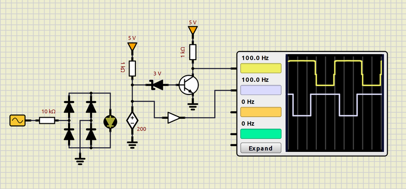
Quote from Defran on March 10, 2024, 9:14 pmHere is another idea to get the edges of the signal more vertical.
You did well. Thank you.
But, you know, adding a transistor increases the cost of production.
Quote from arcachofo on March 10, 2024, 9:38 pmWould you please replace the manual voltage source with a 100 Hz triangular signal to flip an LED at every edge detection?
Sure:
Would you please replace the manual voltage source with a 100 Hz triangular signal to flip an LED at every edge detection?
Sure:
Uploaded files:
Quote from KerimF on March 10, 2024, 9:43 pmQuote from arcachofo on March 10, 2024, 9:38 pmWould you please replace the manual voltage source with a 100 Hz triangular signal to flip an LED at every edge detection?
Sure:
Thank you for your fast reply.
Quote from arcachofo on March 10, 2024, 9:38 pmWould you please replace the manual voltage source with a 100 Hz triangular signal to flip an LED at every edge detection?
Sure:
Thank you for your fast reply.
Quote from KerimF on March 10, 2024, 9:53 pmAs you said, it worked.
So, I will try to find out why it did work with my code with a square wave only.
In any case, I will be back later... It is around 1 AM here.
Good night.
As you said, it worked.
So, I will try to find out why it did work with my code with a square wave only.
In any case, I will be back later... It is around 1 AM here.
Good night.
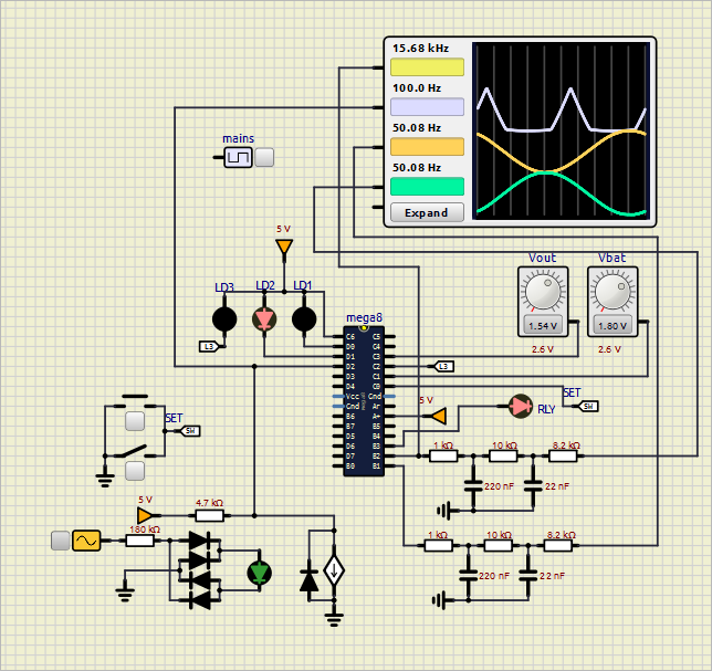
Quote from KerimF on March 11, 2024, 10:39 amSorry, I had to upload my work since I couldn’t discover the root of the problem.
As you will see on the uploaded schematic, a triangular wave generator (turned on) is connected to INT0 pin.
After running the code, LED2 will start blinking (turning on and off) to signal the presence of the mains voltage. Then, after a while, the MCU stops generating the two sine waves.
And by deactivating the triangular wave generator, the MCU, also after a while, resumes outputting the sine waves.Now, the debugger needs to be stopped in order to change the schematic.
First, the connection between the triangular wave generator and the INT0 pin is removed. Then the controlled source will be connected as shown on the photo above (uploaded previously).
By running again the code, LED2 stays in the on state, as if no signal is present at INT0 pin.
For instance, at line 1073 of the code, the state of INTF0 flag is checked continuously (since the interrupt routine of INT0 is disabled). And at line 543, MCUCR is set for the falling edge mode.Thank you.
Sorry, I had to upload my work since I couldn’t discover the root of the problem.
As you will see on the uploaded schematic, a triangular wave generator (turned on) is connected to INT0 pin.
After running the code, LED2 will start blinking (turning on and off) to signal the presence of the mains voltage. Then, after a while, the MCU stops generating the two sine waves.
And by deactivating the triangular wave generator, the MCU, also after a while, resumes outputting the sine waves.
Now, the debugger needs to be stopped in order to change the schematic.
First, the connection between the triangular wave generator and the INT0 pin is removed. Then the controlled source will be connected as shown on the photo above (uploaded previously).
By running again the code, LED2 stays in the on state, as if no signal is present at INT0 pin.
For instance, at line 1073 of the code, the state of INTF0 flag is checked continuously (since the interrupt routine of INT0 is disabled). And at line 543, MCUCR is set for the falling edge mode.
Thank you.
Uploaded files: