
ATmega16 ADC simultion partly work on 0.1.7 SImulIDE and did`t work on 1.1.0 - SR0 ver.
Quote from NickNameNemo on April 11, 2024, 10:15 amHi
Could anybody help me with problem with SimulIDE ?
OS Name Ubuntu 20.04.6 LST
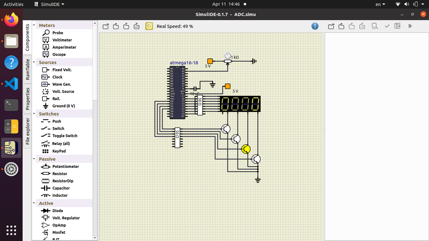
Precompiled SimulIDE 0.1.7
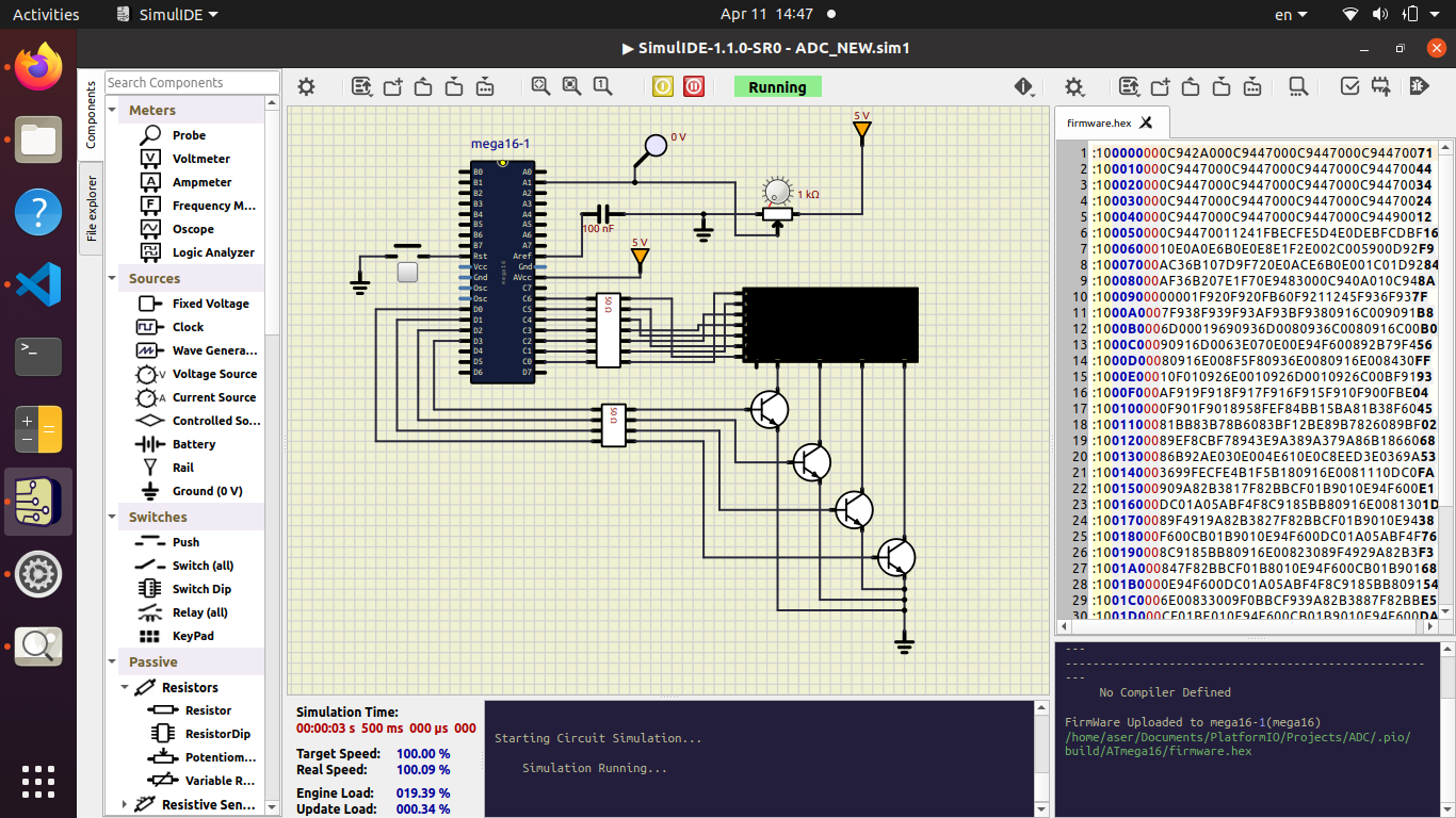
recently downloaded SImulIDE 1.1.0 -SR0
On old version my code partly work (display zeros on 7-segment display but not display ADC value
on new version display noting even I draw new circuit from scratch.
my code
#include <avr/io.h>
#include <avr/interrupt.h>
#include <stdint.h>

#define DISPLAY PORTC
#define DIGIT_0 PIND0
#define DIGIT_1 PIND1
#define DIGIT_2 PIND2
#define DIGIT_3 PIND3
#define SELECTOR PORTD

#define TIMER_COMPARE_VALUE 249
#define DISPLAY_DELAY  3


volatile uint8_t numbers[] = {0x3f, 0x06, 0x5b, 0x4f, 0x66, 0x6d, 0x7d, 0x07, 0x7f, 0x6f, 0x40};
volatile uint16_t timer = 0;
volatile uint8_t digit = 0;

void initialize_timer(void) {
    TCCR0 |= (1 << CS01) | (1 << CS00) | (1 << WGM01); // prescale 64, CTC mode
    TCNT0 = 0x00;
    TIMSK |= (1 << OCIE0); // compare match interrupt enable
    OCR0 = TIMER_COMPARE_VALUE; // 1ms interrupt
    sei(); // enable global interrupts
}


void initalize_ports(void) {

    DDRC = 0xFF;
    PORTC = 0x00;
    DDRD |= (1<<PIND0) | (1<<PIND1) | (1<<PIND2) | (1<<PIND3);

}

void initalize_adc(void) {

    ADMUX |= (1<< REFS0); //AVCC with external capacitor at AREF pin
    ADMUX |= (1<<MUX0);
    ADCSRA |= (1<<ADEN); // ADC enable
    ADCSRA |= (1<< ADPS1) | (1<<ADPS2); // prescale 64

}

uint16_t adc_read(void) {

    ADCSRA |= (1<< ADSC); // ADC start convertion
    while(ADCSRA & (1<<ADSC));
    return ADC;
}

void delay(void) {
    timer++;
    if (timer % DISPLAY_DELAY == 0) {
        digit++;
        if(digit > 3) {
            digit = 0;
        }
        timer = 0;
    }

}

void display_digit(volatile uint8_t *port, uint16_t number) {

    if(digit == 0) {
        SELECTOR |= (1<<DIGIT_0);
        SELECTOR &=~ ((1<<DIGIT_1) | (1<<DIGIT_2) | (1<<DIGIT_3));
        *port = numbers[number % 10];
    }
    if(digit == 1) {
        SELECTOR |= (1<<DIGIT_1);
        SELECTOR &=~ ((1<<DIGIT_0) | (1<<DIGIT_2) | (1<<DIGIT_3));
        *port = numbers[(number /10) % 10];
    }
    if(digit == 2) {
        SELECTOR |= (1<<DIGIT_2);
        SELECTOR &=~ ((1<<DIGIT_1) | (1<<DIGIT_0) | (1<<DIGIT_3));
        *port = numbers[(number /100) % 10];
    }
    if(digit == 3) {
        SELECTOR |= (1<<DIGIT_3);
        SELECTOR &=~ ((1<<DIGIT_1) | (1<<DIGIT_2) | (1<<DIGIT_0));
        *port = numbers[(number / 1000) % 10];
    }


}

ISR(TIMER0_COMP_vect) {
    delay();
}


int main(void)
{
    initalize_ports();
    initialize_timer();
    initalize_adc();
    while (1)
    {

        display_digit(&DISPLAY, adc_read());

    }

    return 0;
}
thanks.
Hi
Could anybody help me with problem with SimulIDE ?
OS Name Ubuntu 20.04.6 LST
Precompiled SimulIDE 0.1.7
recently downloaded SImulIDE 1.1.0 -SR0
On old version my code partly work (display zeros on 7-segment display but not display ADC value
on new version display noting even I draw new circuit from scratch.
my code
#include <avr/io.h>
#include <avr/interrupt.h>
#include <stdint.h>

#define DISPLAY PORTC
#define DIGIT_0 PIND0
#define DIGIT_1 PIND1
#define DIGIT_2 PIND2
#define DIGIT_3 PIND3
#define SELECTOR PORTD

#define TIMER_COMPARE_VALUE 249
#define DISPLAY_DELAY  3


volatile uint8_t numbers[] = {0x3f, 0x06, 0x5b, 0x4f, 0x66, 0x6d, 0x7d, 0x07, 0x7f, 0x6f, 0x40};
volatile uint16_t timer = 0;
volatile uint8_t digit = 0;

void initialize_timer(void) {
    TCCR0 |= (1 << CS01) | (1 << CS00) | (1 << WGM01); // prescale 64, CTC mode
    TCNT0 = 0x00;
    TIMSK |= (1 << OCIE0); // compare match interrupt enable
    OCR0 = TIMER_COMPARE_VALUE; // 1ms interrupt
    sei(); // enable global interrupts
}


void initalize_ports(void) {

    DDRC = 0xFF;
    PORTC = 0x00;
    DDRD |= (1<<PIND0) | (1<<PIND1) | (1<<PIND2) | (1<<PIND3);

}

void initalize_adc(void) {

    ADMUX |= (1<< REFS0); //AVCC with external capacitor at AREF pin
    ADMUX |= (1<<MUX0);
    ADCSRA |= (1<<ADEN); // ADC enable
    ADCSRA |= (1<< ADPS1) | (1<<ADPS2); // prescale 64

}

uint16_t adc_read(void) {

    ADCSRA |= (1<< ADSC); // ADC start convertion
    while(ADCSRA & (1<<ADSC));
    return ADC;
}

void delay(void) {
    timer++;
    if (timer % DISPLAY_DELAY == 0) {
        digit++;
        if(digit > 3) {
            digit = 0;
        }
        timer = 0;
    }

}

void display_digit(volatile uint8_t *port, uint16_t number) {

    if(digit == 0) {
        SELECTOR |= (1<<DIGIT_0);
        SELECTOR &=~ ((1<<DIGIT_1) | (1<<DIGIT_2) | (1<<DIGIT_3));
        *port = numbers[number % 10];
    }
    if(digit == 1) {
        SELECTOR |= (1<<DIGIT_1);
        SELECTOR &=~ ((1<<DIGIT_0) | (1<<DIGIT_2) | (1<<DIGIT_3));
        *port = numbers[(number /10) % 10];
    }
    if(digit == 2) {
        SELECTOR |= (1<<DIGIT_2);
        SELECTOR &=~ ((1<<DIGIT_1) | (1<<DIGIT_0) | (1<<DIGIT_3));
        *port = numbers[(number /100) % 10];
    }
    if(digit == 3) {
        SELECTOR |= (1<<DIGIT_3);
        SELECTOR &=~ ((1<<DIGIT_1) | (1<<DIGIT_2) | (1<<DIGIT_0));
        *port = numbers[(number / 1000) % 10];
    }


}

ISR(TIMER0_COMP_vect) {
    delay();
}


int main(void)
{
    initalize_ports();
    initialize_timer();
    initalize_adc();
    while (1)
    {

        display_digit(&DISPLAY, adc_read());

    }

    return 0;
}
thanks.
Quote from NickNameNemo on April 11, 2024, 5:31 pmHi,
Could you please explain?
Hi,
Could you please explain?
Quote from NickNameNemo on April 12, 2024, 4:20 amDear arcachofo thank you for help.
Simulation starts working, but partly (only lowest digit shows value).
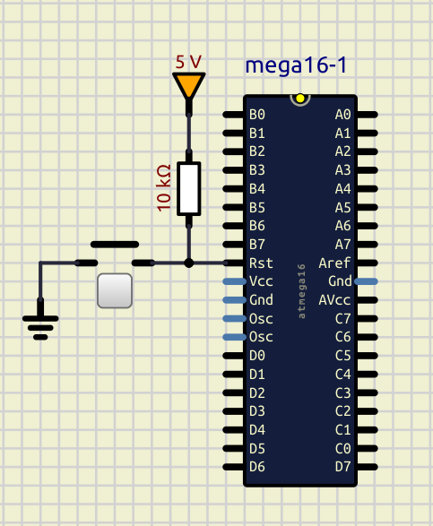
could you please explain why rst should be connected to +5 V?
Is there any information in Atmega datasheet?
Thank you!
Dear arcachofo thank you for help.
Simulation starts working, but partly (only lowest digit shows value).
could you please explain why rst should be connected to +5 V?
Is there any information in Atmega datasheet?
Thank you!
Quote from arcachofo on April 12, 2024, 6:20 pmHi.
Simulation starts working, but partly (only lowest digit shows value).
I see...
There is an error in some configuration files for atmega16.
You can try to add files attached to simulide data folder.
Merge data folder attached with SimulIDE_1.1.0-SR0/data
Then open simulide and try your circuit.
could you please explain why rst should be connected to +5 V?
Because Reset pin internal pull-up resistor in AVRs is not simulated in simulide.
Hi.
Simulation starts working, but partly (only lowest digit shows value).
I see...
There is an error in some configuration files for atmega16.
You can try to add files attached to simulide data folder.
Merge data folder attached with SimulIDE_1.1.0-SR0/data
Then open simulide and try your circuit.
could you please explain why rst should be connected to +5 V?
Because Reset pin internal pull-up resistor in AVRs is not simulated in simulide.
Uploaded files:
Quote from NickNameNemo on April 13, 2024, 8:35 amDear arcachofo
Thank you a lot!
Now simulation works!
Best regards!
Dear arcachofo
Thank you a lot!
Now simulation works!
Best regards!