A four-diode bridge not working. What am I doing wrong?
Quote from blitobyte on March 21, 2024, 11:35 amHi,
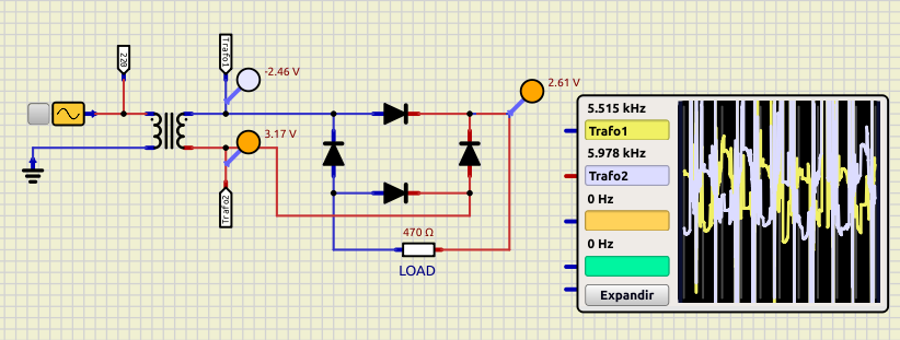
I'm doing a 'practice' about a voltage source with a 4-diode bridge. After the diode bridge and before the capacitor filter, I should get a 'dragon's crest' but I don't. What am I doing wrong?
I'm attaching the sim file and and image.
Thanks.
Hi,
I'm doing a 'practice' about a voltage source with a 4-diode bridge. After the diode bridge and before the capacitor filter, I should get a 'dragon's crest' but I don't. What am I doing wrong?
I'm attaching the sim file and and image.

Thanks.
Uploaded files:
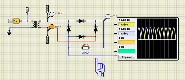
Quote from Defran on March 21, 2024, 1:06 pmYou have to put a reference to GROUND: By connecting the negative output of the bridge to ground or by connecting this output to the ground of the oscilloscope. In reality you also have to do it like this (Two probes without ground only see ELECTRICAL NOISE)
You have to put a reference to GROUND: By connecting the negative output of the bridge to ground or by connecting this output to the ground of the oscilloscope. In reality you also have to do it like this (Two probes without ground only see ELECTRICAL NOISE)

Quote from Defran on March 22, 2024, 12:33 amGood, but keep in mind that in your diagram this happens because the transformer produces a galvanic isolation that makes the ground also isolated, otherwise the ground connection of the oscilloscope would not be necessary because in Simulide it is connected to a general ground by default .
Good, but keep in mind that in your diagram this happens because the transformer produces a galvanic isolation that makes the ground also isolated, otherwise the ground connection of the oscilloscope would not be necessary because in Simulide it is connected to a general ground by default .
