
6502 SBC
Quote from Wim97 on June 18, 2025, 9:07 amHi All. First I love SimulIDE!
A few years ago I build my own 6502 single board computer. Of course inspired by ben eater. Mainly based on a junior from elektor. Programed de OS for it, the thing works. Me Happy.
But I wanted more (DMA, sound, video, game, more ram/rom,serial etc) designed a lot. Never made it.
Recently I discovered SimulIDE and I could simulate my own 6502 computer with it and test al the extra's.
Only I may discovered some bugs (Note it could be I use simulIDE wrong), I use latest test version 2069.
- my own computer uses timing IRQ from a 6532 to interrupt the 6502 to display stuff on lcd. I noticed that the IRQ (and NMI) routine don't work in the 6502.
- I added a 6522 for a joystick interface but inputing data on the ports doesn't work.
- The 6522 should disconnect from the databus if the CS's aren't selecting the 6522 they stay connected and fight on the databus.
Thanks.
Hi All. First I love SimulIDE!
A few years ago I build my own 6502 single board computer. Of course inspired by ben eater. Mainly based on a junior from elektor. Programed de OS for it, the thing works. Me Happy.
But I wanted more (DMA, sound, video, game, more ram/rom,serial etc) designed a lot. Never made it.
Recently I discovered SimulIDE and I could simulate my own 6502 computer with it and test al the extra's.
Only I may discovered some bugs (Note it could be I use simulIDE wrong), I use latest test version 2069.
- my own computer uses timing IRQ from a 6532 to interrupt the 6502 to display stuff on lcd. I noticed that the IRQ (and NMI) routine don't work in the 6502.
- I added a 6522 for a joystick interface but inputing data on the ports doesn't work.
- The 6522 should disconnect from the databus if the CS's aren't selecting the 6522 they stay connected and fight on the databus.
Thanks.
Quote from arcachofo on June 18, 2025, 10:45 amHi.
Thanks for reporting.All 65xx don't have much testing, specially 6520/22/32.
And some features might not be implemented.my own computer uses timing IRQ from a 6532 to interrupt the 6502 to display stuff on lcd. I noticed that the IRQ (and NMI) routine don't work in the 6502.
Do you think it's the 6502 not working or the 6532 not generating the interrupt?
I think 6532 is the least tested, don't remember if it even works at all.
I added a 6522 for a joystick interface but inputing data on the ports doesn't work.
6522 is used in the example: examples/Micro/mcs-65/6502_ben/6502_ben.sim1
And seems to be working there, maybe you can share some not working case.
The 6522 should disconnect from the databus if the CS's aren't selecting the 6522 they stay connected and fight on the databus.
As far as I can remember, CS lines are used in RW operations.
If a Port is configured as output it will remain driving the bus despite of the state of CS's.
Hi.
Thanks for reporting.
All 65xx don't have much testing, specially 6520/22/32.
And some features might not be implemented.
my own computer uses timing IRQ from a 6532 to interrupt the 6502 to display stuff on lcd. I noticed that the IRQ (and NMI) routine don't work in the 6502.
Do you think it's the 6502 not working or the 6532 not generating the interrupt?
I think 6532 is the least tested, don't remember if it even works at all.
I added a 6522 for a joystick interface but inputing data on the ports doesn't work.
6522 is used in the example: examples/Micro/mcs-65/6502_ben/6502_ben.sim1
And seems to be working there, maybe you can share some not working case.
The 6522 should disconnect from the databus if the CS's aren't selecting the 6522 they stay connected and fight on the databus.
As far as I can remember, CS lines are used in RW operations.
If a Port is configured as output it will remain driving the bus despite of the state of CS's.
Quote from Wim97 on June 18, 2025, 12:10 pmI made push buttons directly on the 6502 to activate the NMI and IRQ lines (same as the reset button for instance). but the program goes on without going to the interrupt routine ($FFFD etc jump area's)
the 6532 gives output, I don't know if the input or the timing works (my keypad is connected to the 6532 input but I stop testing when I saw that I the interrupt vectors don't work).
The ben eater example uses the 6522 as output's. but good point why doesn't the databus fight in that example?! Found it, if you make input on the port it goes wrong.
If a Port is configured as output it will remain driving the bus despite of the state of CS's.
True, but the databus should be high impedance.
Here from the 6522 data sheet "The 8 bi-directional data bus lines are used to transfer data between the MCS6522 and the system
processor. The internal drivers will remain in the high-impedance state except when the chip is selected
(CS1 = 1, CS2 = 0), Read/Write is high and the Phase Two Clock is high. At this time, the contents of
the selected register are placed on the data bus. "I can't attach pictures, i eddited ben's example a bit. With IRQ switch and also the databus is fighting on the 6522.
I made push buttons directly on the 6502 to activate the NMI and IRQ lines (same as the reset button for instance). but the program goes on without going to the interrupt routine ($FFFD etc jump area's)
the 6532 gives output, I don't know if the input or the timing works (my keypad is connected to the 6532 input but I stop testing when I saw that I the interrupt vectors don't work).
The ben eater example uses the 6522 as output's. but good point why doesn't the databus fight in that example?! Found it, if you make input on the port it goes wrong.
If a Port is configured as output it will remain driving the bus despite of the state of CS's.
True, but the databus should be high impedance.
Here from the 6522 data sheet "The 8 bi-directional data bus lines are used to transfer data between the MCS6522 and the system
processor. The internal drivers will remain in the high-impedance state except when the chip is selected
(CS1 = 1, CS2 = 0), Read/Write is high and the Phase Two Clock is high. At this time, the contents of
the selected register are placed on the data bus. "
I can't attach pictures, i eddited ben's example a bit. With IRQ switch and also the databus is fighting on the 6522.
Uploaded files:
Quote from arcachofo on June 19, 2025, 5:09 amOk thanks, now I see the problem.
I did some changes to address the CS issue, you can replace the file Simulide/data/MCS65/6522/6522_core.as with the one attached.
If this works then we can have a look at the IRQ problem.
Ok thanks, now I see the problem.
I did some changes to address the CS issue, you can replace the file Simulide/data/MCS65/6522/6522_core.as with the one attached.
If this works then we can have a look at the IRQ problem.
Quote from Wim97 on June 19, 2025, 7:59 amI think the Phi1 signal stays low on the 6502. "The 65CE02 requires an external. TTL-level Phi0 clock
Two full level clocks (Phi1 and Phi2 ) are generated by the 65CEC2 Phi2 in phase with Phi0 and Phi1 180 degrees out
of phase with Phi0"I can't test assembly code at the moment, but I made a memory check routine on my real SBC. I was testing it and it didn't work in simulation (I tested it last week) from memory this code goes wrong:
LDA #$00
STA $80
LDA #$20
STA $81
LDY #$01
LDA#$AA
STA($80),Y ; this one goes wrong opcode $91. It should store #$AA in address $2001
"A9 00 85 80 A9 20 85 81 A0 01 A9 AA 91 80"
:), I tried to save ben eaters rom to modify it a bit, I get this:
-94, -1,-102, -87, -1,-115, 2, 96, -87, -32,-115, 3, 96, -87, 56, 32
97,-128, -87, 14, 32, 97,-128, -87, 6, 32, 97,-128, -87, 1, 32, 97
-128, -94, 0, -67, 50,-128, -16, 7, 32, 119,-128, -24, 76, 35,-128, 76
47,-128, 72, 101, 108, 108, 111, 44, 32, 119, 111, 114, 108, 100, 33, 0
72, -87, 0,-115, 2, 96, -87, 64,-115, 1, 96, -87, -64,-115, 1, 96Sorry :).
I think the Phi1 signal stays low on the 6502. "The 65CE02 requires an external. TTL-level Phi0 clock
Two full level clocks (Phi1 and Phi2 ) are generated by the 65CEC2 Phi2 in phase with Phi0 and Phi1 180 degrees out
of phase with Phi0"
I can't test assembly code at the moment, but I made a memory check routine on my real SBC. I was testing it and it didn't work in simulation (I tested it last week) from memory this code goes wrong:
LDA #$00
STA $80
LDA #$20
STA $81
LDY #$01
LDA#$AA
STA($80),Y ; this one goes wrong opcode $91. It should store #$AA in address $2001
"A9 00 85 80 A9 20 85 81 A0 01 A9 AA 91 80"
:), I tried to save ben eaters rom to modify it a bit, I get this:
-94, -1,-102, -87, -1,-115, 2, 96, -87, -32,-115, 3, 96, -87, 56, 32
97,-128, -87, 14, 32, 97,-128, -87, 6, 32, 97,-128, -87, 1, 32, 97
-128, -94, 0, -67, 50,-128, -16, 7, 32, 119,-128, -24, 76, 35,-128, 76
47,-128, 72, 101, 108, 108, 111, 44, 32, 119, 111, 114, 108, 100, 33, 0
72, -87, 0,-115, 2, 96, -87, 64,-115, 1, 96, -87, -64,-115, 1, 96
Sorry :).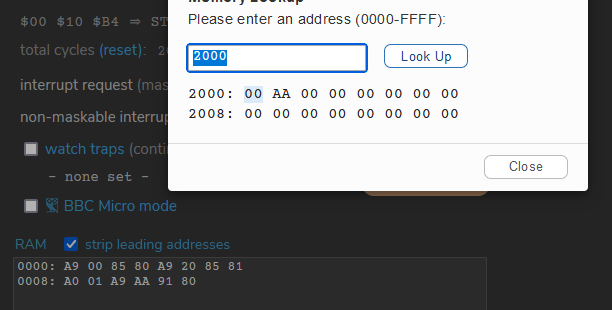
Uploaded files:
Quote from arcachofo on June 19, 2025, 8:31 amQuote from Wim97 on June 19, 2025, 7:59 amI think the Phi1 signal stays low on the 6502. "The 65CE02 requires an external. TTL-level Phi0 clock
Two full level clocks (Phi1 and Phi2 ) are generated by the 65CEC2 Phi2 in phase with Phi0 and Phi1 180 degrees out
of phase with Phi0"I can't test assembly code at the moment, but I made a memory check routine on my real SBC but in the simulation it goes wrong.
It this kind of code:
LDA #$00
STA $80
LDA #$20
STA $81
LDY #$01
LDA#$AA
STA($80),Y ; this one goes wrong opcode $91
Not sure what are you doing.
Where is that code?
The circuit you share seems to have the hello_world example in ROM and nothing else.
Quote from Wim97 on June 19, 2025, 7:59 amI think the Phi1 signal stays low on the 6502. "The 65CE02 requires an external. TTL-level Phi0 clock
Two full level clocks (Phi1 and Phi2 ) are generated by the 65CEC2 Phi2 in phase with Phi0 and Phi1 180 degrees out
of phase with Phi0"I can't test assembly code at the moment, but I made a memory check routine on my real SBC but in the simulation it goes wrong.
It this kind of code:
LDA #$00
STA $80
LDA #$20
STA $81
LDY #$01
LDA#$AA
STA($80),Y ; this one goes wrong opcode $91
Not sure what are you doing.
Where is that code?
The circuit you share seems to have the hello_world example in ROM and nothing else.
Quote from arcachofo on June 19, 2025, 8:36 amFor your las edit I guess that STA($80),Y ; is working...
About phi1: it is not simulated.
Is it really needed?
For your las edit I guess that STA($80),Y ; is working...
About phi1: it is not simulated.
Is it really needed?
Quote from Wim97 on June 19, 2025, 9:25 amPhi1: I don't think so, I'm working on a apple-ii schematic and they don't even use the Phi1 and Phi2 because of timing problems. It's just for completeness, Vic20, Kim, Junior also doesn't use Phi1. A quick search only apple-1 uses it for some clock generation magic.. Strange.
I can't compile/edit code at the moment. I will try that this evening.
Phi1: I don't think so, I'm working on a apple-ii schematic and they don't even use the Phi1 and Phi2 because of timing problems. It's just for completeness, Vic20, Kim, Junior also doesn't use Phi1. A quick search only apple-1 uses it for some clock generation magic.. Strange.
I can't compile/edit code at the moment. I will try that this evening.
Quote from Wim97 on June 19, 2025, 4:45 pmAll,
I made a new modified ben eater with the IRQ/NMI/BRK bugs, also there is something wrong whit the STA(ZP),Y instruction.
It changes address $2000 to #$FF and address $2001 to #$AA, it shouldn't touch adress $2000??
The command BRK does some weird things, it is a kind of softinterrupt which follows the NMI vectors. But it goes to adress$34xx??
All,
I made a new modified ben eater with the IRQ/NMI/BRK bugs, also there is something wrong whit the STA(ZP),Y instruction.
It changes address $2000 to #$FF and address $2001 to #$AA, it shouldn't touch adress $2000??
The command BRK does some weird things, it is a kind of softinterrupt which follows the NMI vectors. But it goes to adress$34xx??
Uploaded files: