
230Vac, semi amplitude 320V, midle voltage 0V
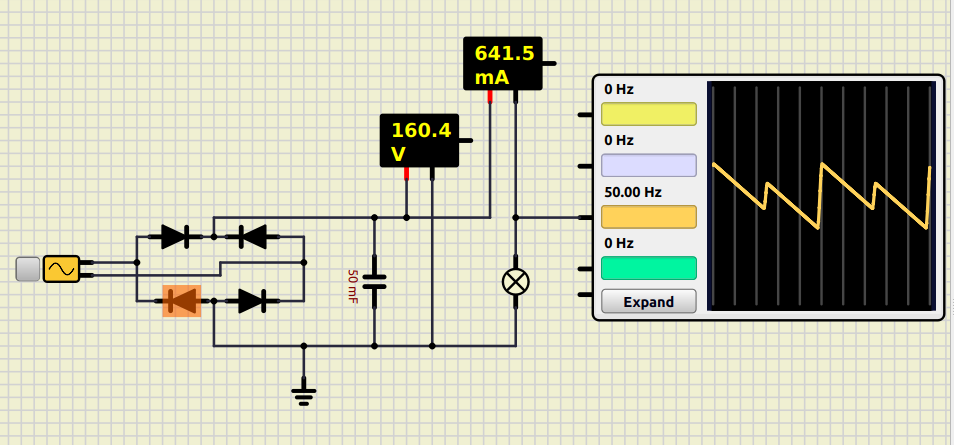
Quote from feri on February 11, 2025, 7:38 pmFrom this circuit I expected about 230Vcc, but I get 160Vcc.
In addition the diodes flash and I do not understand which values to change.
The oscilloscope detects 50Hz even if in Vcc (At most they should be 100Hz).
Greetings
From this circuit I expected about 230Vcc, but I get 160Vcc.
In addition the diodes flash and I do not understand which values to change.
The oscilloscope detects 50Hz even if in Vcc (At most they should be 100Hz).
Greetings
Uploaded files:Quote from arcachofo on February 12, 2025, 8:16 amIn addition the diodes flash and I do not understand which values to change.
Diode flash means maximum current surpassed.
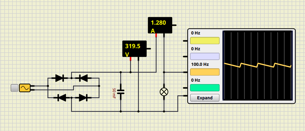
About other issues, the simplest thing you can do is to remove the ground and connect Oscilloscope Ref. pin, like this:
In addition the diodes flash and I do not understand which values to change.
Diode flash means maximum current surpassed.
About other issues, the simplest thing you can do is to remove the ground and connect Oscilloscope Ref. pin, like this:
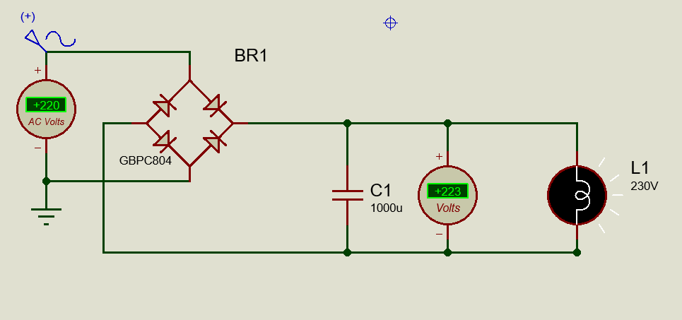
Quote from feri on May 4, 2025, 7:28 pmBy setting the half-amplitude of the wave to 320 volts and putting a rectifier bridge I get paired half-waves of amplitude 320 volts but if I put a capacitor such as 2000 uF and a load such as a light bulb I should get a continuous voltage of 320/1.41 = 226 Vcc while I get a voltage of about 320 Vcc. Tests done with proteus confirm the formula 320/1.41 = 226 Vcc.
Greetings
By setting the half-amplitude of the wave to 320 volts and putting a rectifier bridge I get paired half-waves of amplitude 320 volts but if I put a capacitor such as 2000 uF and a load such as a light bulb I should get a continuous voltage of 320/1.41 = 226 Vcc while I get a voltage of about 320 Vcc. Tests done with proteus confirm the formula 320/1.41 = 226 Vcc.
Greetings
Uploaded files:
Quote from arcachofo on May 4, 2025, 11:19 pmNormally if you rectify an AC voltage you get close to the peak voltage, or a little bit less depending on the voltage drop in diodes and resistances.
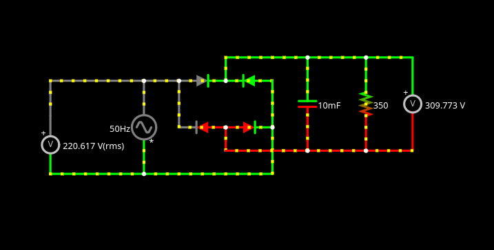
Not sure what you are doing in Proteus, but I get similar results in Falstad Simulator:
AC Voltage source: 220V RMS (312V peak).
Normally if you rectify an AC voltage you get close to the peak voltage, or a little bit less depending on the voltage drop in diodes and resistances.
Not sure what you are doing in Proteus, but I get similar results in Falstad Simulator:
AC Voltage source: 220V RMS (312V peak).
Quote from KerimF on May 4, 2025, 11:44 pmQuote from feri on May 4, 2025, 7:28 pmBy setting the half-amplitude of the wave to 320 volts and putting a rectifier bridge I get paired half-waves of amplitude 320 volts but if I put a capacitor such as 2000 uF and a load such as a light bulb I should get a continuous voltage of 320/1.41 = 226 Vcc while I get a voltage of about 320 Vcc. Tests done with proteus confirm the formula 320/1.41 = 226 Vcc.
Greetings
What is the resistance of L1?

Quote from feri on May 4, 2025, 7:28 pmBy setting the half-amplitude of the wave to 320 volts and putting a rectifier bridge I get paired half-waves of amplitude 320 volts but if I put a capacitor such as 2000 uF and a load such as a light bulb I should get a continuous voltage of 320/1.41 = 226 Vcc while I get a voltage of about 320 Vcc. Tests done with proteus confirm the formula 320/1.41 = 226 Vcc.
Greetings
What is the resistance of L1?
Quote from KerimF on May 4, 2025, 11:55 pmQuote from arcachofo on May 4, 2025, 11:19 pmNormally if you rectify an AC voltage you get close to the peak voltage, or a little bit less depending on the voltage drop in diodes and resistances.
And by adding a load, as the L1 on Feri schematic, there will be a voltage ripple on the capacitor that decreases its average voltage.
Quote from arcachofo on May 4, 2025, 11:19 pmNormally if you rectify an AC voltage you get close to the peak voltage, or a little bit less depending on the voltage drop in diodes and resistances.
And by adding a load, as the L1 on Feri schematic, there will be a voltage ripple on the capacitor that decreases its average voltage.
Quote from arcachofo on May 5, 2025, 12:00 amQuote from KerimF on May 4, 2025, 11:55 pmQuote from arcachofo on May 4, 2025, 11:19 pmNormally if you rectify an AC voltage you get close to the peak voltage, or a little bit less depending on the voltage drop in diodes and resistances.
And by adding a load, as the L1 on Feri schematic, there will be a voltage ripple on the capacitor that decreases its average voltage.
Yes, I guess the capacitor discharges between peaks.
Quote from KerimF on May 4, 2025, 11:55 pmQuote from arcachofo on May 4, 2025, 11:19 pmNormally if you rectify an AC voltage you get close to the peak voltage, or a little bit less depending on the voltage drop in diodes and resistances.
And by adding a load, as the L1 on Feri schematic, there will be a voltage ripple on the capacitor that decreases its average voltage.
Yes, I guess the capacitor discharges between peaks.
Quote from feri on May 5, 2025, 5:42 pmYes indeed the voltage varies with the variation of the resistance of the bulb and therefore of the current. But then how do you measure the rms vca voltage.
Quote from arcachofo on May 6, 2025, 8:37 amQuote from feri on May 5, 2025, 5:42 pmYes indeed the voltage varies with the variation of the resistance of the bulb and therefore of the current. But then how do you measure the rms vca voltage.By now there is no RMS voltmeter in Simulide.
Quote from feri on May 5, 2025, 5:42 pmYes indeed the voltage varies with the variation of the resistance of the bulb and therefore of the current. But then how do you measure the rms vca voltage.
By now there is no RMS voltmeter in Simulide.